The Problem: Charging a 14kWh House Battery from the Alternator
If you’re building a van, sooner or later you’ll ask yourself: Can I charge my house battery from the alternator? That’s exactly what I set out to do. When ordering the vehicle one of the options I could choose is to factory-equip it with dual 250A alternators. For under a thousand dollars, it seemed like a great deal.
Unfortunately, things weren’t that simple.
Ford’s system uses smart alternators, meaning the vehicle computer selectively enables the second alternator and regulates voltage based on various factors, such as the charge state of the AGM starter battery. While you might expect to access the full 500A from the dual alternator setup, Ford officially limits output to 175A via the CCP2 connection point. Worse, the voltage varies unpredictably, which is a major issue for charging a secondary system.
Had I known these limitations when ordering the van, I would have skipped the upgrade and opted for a third-party 24V alternator, such as those offered by Nation or APS. However, removing a factory alternator in the dual-alternator configuration causes a check engine light—so for now, I had to make it work.
Ford’s “Third Party High Power Mode” (TPHPM): A Workaround
One way to override Ford’s smart charging system is by enabling Third Party High Power Mode (TPHPM). This mode forces the alternator to output a stable voltage (>14V), bypassing the system’s variable behavior.
TPHPM can be activated by grounding a specific pin in the C33-E 10-way connector, located under the driver’s seat. Here are some helpful forum threads for more details:
The 12V to 24V Dilemma & Charging Approaches
The van’s system runs on 12V (AGM batteries), while my house battery is a 24V LiFePo4 system. This mismatch means I couldn’t simply wire the alternator output directly to my house battery. The two most common solutions are:
- DC-DC Chargers: Victron and Sterling make chargers that step up 12V to 24V. However, they require large cables and can be expensive.
- The “Orton Method”: A clever workaround that converts 12V DC to 110V AC (via an inverter), then back to 24V DC using a standard shore power charger (e.g., Victron Multiplus). This approach offers key advantages:
- Redundancy: If my house battery or inverter dies, I can still generate 110V AC from the alternator-fed inverter.
- Smaller cables: Instead of running bulky DC cables carrying 80-175A, I only need a 15-20A AC cable from front to back.
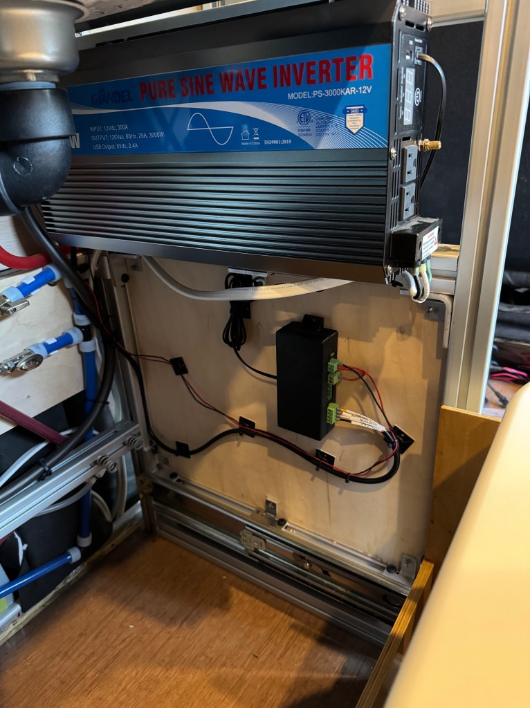
- Cost savings: The Giandel 3000W pure sine wave inverter ($300) was far cheaper than a Sterling BB1224120 DC-DC charger (~$1000).
My Alternator Charging System Requirements
I wanted a system that:
- Allowed easy on/off control (via a physical button and HomeAssistant automations)
- Automatically enabled Third Party High Power Mode when charging
- Used the Giandel inverter since many other forum members have had good results with it feeding the Victron Multiplus
Clearly the best way to accomplish this? A custom ESP32-based controller.
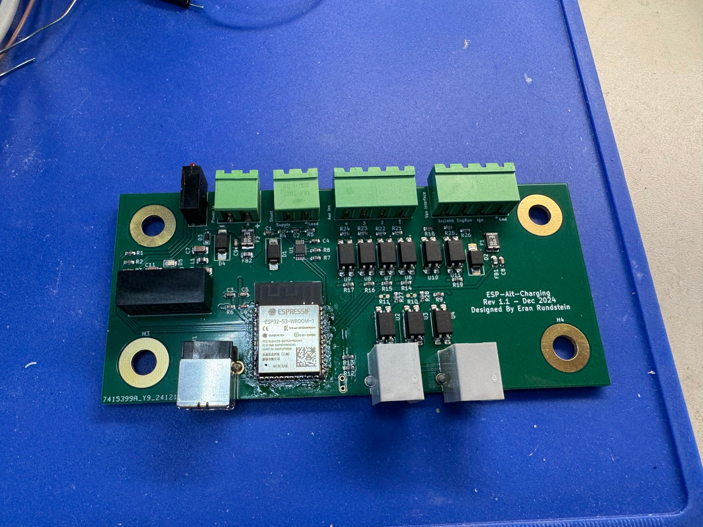
Introducing the ESP-Alt-Charging Board
To automate this setup, I designed a custom ESP32-based circuit board—because over-engineering is the name of the game in this never-ending van build hobby. This project is based on work by a forum user called brio (link here).


Features of the ESP-Alt-Charging Board
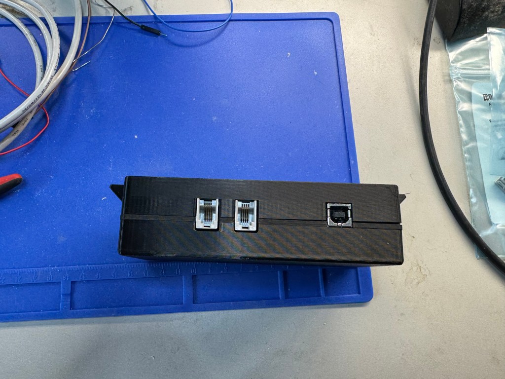
- Control over the Giandel inverter: The remote connection is a simple pass-through, ensuring manual control remains available.
- Integration with the C33-E connector:
- GND, SRC Inhibit, Engine Run, Ignition
- Enables automatic activation of Third Party High Power Mode
- Detects engine state to manage inverter power automatically
- Shunt support for measuring current and voltage into the inverter (still testing this feature – voltage measurement works reliably but I haven’t wired a shunt yet for current measurement)
- Power flexibility: Uses an isolated DC-DC converter (12-24V), keeping the house and van electrical systems separate (if choosing to power it from the house battery. I chose to power it from CCP2).
- Four auxiliary inputs: Allows integration with Ford’s aux switches, exposing them in HomeAssistant.
- Optocoupled interfaces: Providing electrical isolation for safety.
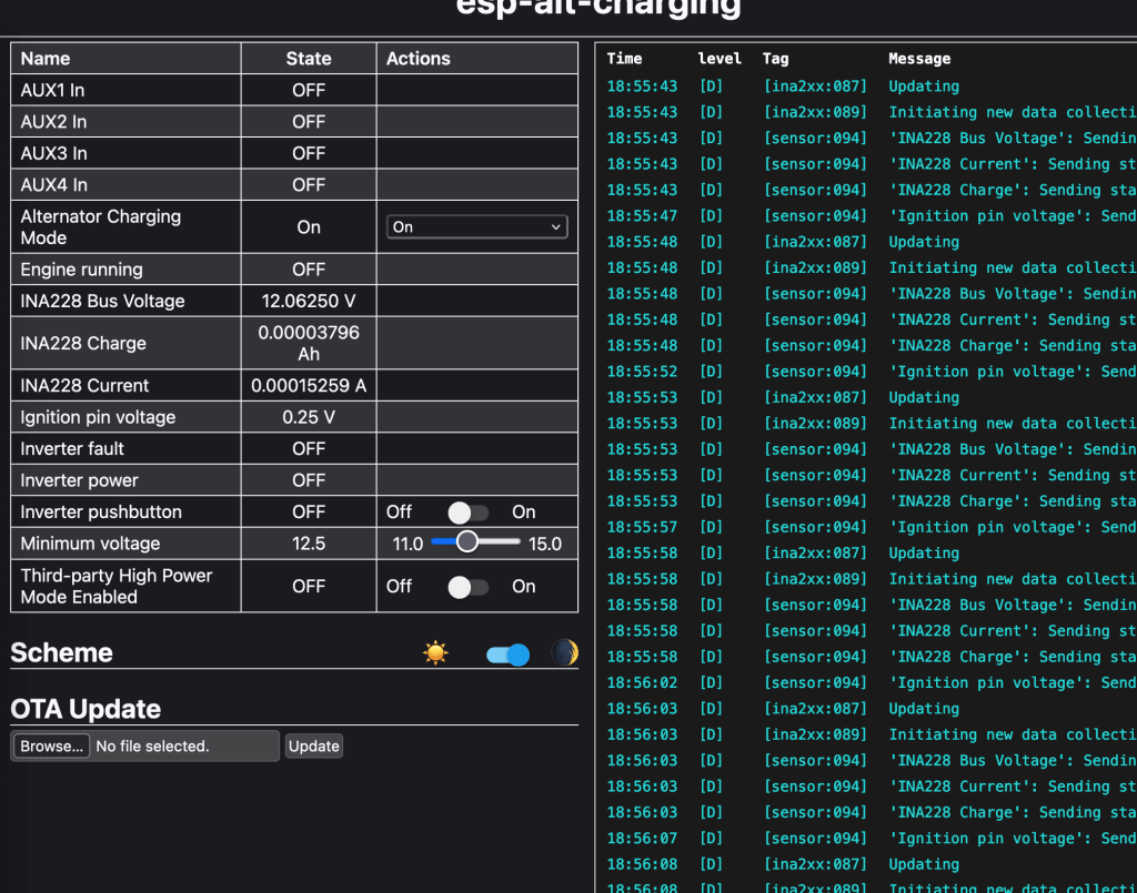
Operating Modes
The ESPHome firmware I’m developing offers three modes:
- Manual: No automation—everything is controlled via HomeAssistant, the web UI or the physical Giandel remote
- On: If the inverter is off, the board will attempt to turn it on, provided conditions (e.g., voltage thresholds, engine running) are met.
- Off: Forces the inverter off if it’s detected as on.
Currently, my setup is configured so that if the inverter is on, Third Party High Power Mode is enabled automatically. When the inverter turns off, TPHPM also turns off. This ensures a seamless, automated charging process.
Current Status
This has been installed on the van but so far I have not tested it other than in my driveway. I was able to verify that the vehicle enters TPHPM by using Forscan (there is some “Charging mode” or something like that PID you can read and see it change). More to come when I get a chance to drive the van around…
This project has been a fun challenge, and while Ford’s smart alternator system isn’t ideal, this setup makes the best of it. If you’re working on a similar build, hopefully, this gives you some ideas!
Got questions or suggestions? Drop a comment!

Leave a comment